
|

Posted on:
30 May 2014
|
In a previous blog post we discussed about constraints and assumptions that describe all kinds of algebraic relationships between process quantities which have to hold at any time.
As mentioned, these assumptions are usually introduced with a goal, namely to simplify the description of the behaviour by neglecting what is considered insignificant in the view of the application one has in mind for the model. Whilst indeed such assumptions do simplify the description, they are also the source of numerous problems, such as “index problems”, which make the solving of the equations very difficult.
We will take a look at an example of an assumption that will lead to a high index model, but first we will look at the same example with no constraining assumptions:
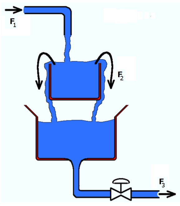
A process consists a mixing tank that flows over into a second tank (see figure). The liquid that is fed to the tank system contains two components (A and B). We are interested in the (dynamic) concentration change of the components (in the first tank) over time.
To keep the explanation simple and easy to follow, the (mass and molar) density will be considered to be constant and we will only consider mass. A well posed system of equations could look as follows (you will see a list of equations. In front of each equation is noted which variable is being solved from this equation):
n_B: d(n_B)/dt = F1_B – F2_B
c_B: c_B * V = n_B
m: m = M_A * n_A + M_B * n_B
V: m = Dm * V
F1_B: F1_B = c_B0 * F1
F2: IF V > Vmax THEN
F2 = K * (V – Vmax)
ELSE
F2 = 0
END
F2_A: F2_A = c_A * F2
F2_B: F2_B = c_B * F2
Where:
n_i :: molar mass of component i, in [mol]
c_i :: molar concentration of component i, in [mol/m3]
m :: total mass, in [kg]
M_i :: molar mass of component I, in [kg/mol]
V :: Volume of system, in [m3]
Dm :: density in [kg/m3]
F# :: Volumetric flow rate of connection #, in [m3/s]
F#_i :: molar mass flow of component i through connection #, in [mol/s]
K :: Constant, in [1/s]
F1 and c_i0 are a function of boundary conditions and can be considered given.
Note: The equations F2 = K * (V – Vmax) is a simplification that seems to work very fine in most situations. It just means that the higher the value of V (above Vmax), the bigger the flow F2 will be. It will automatically find an “equilibrium value”. The K represents a measure for the “resistance to overflow”. If K has a very high value, V will always be close to Vmax.
Let’s now suppose that it was diffcult to find a reliable relation that describes the flow F2 out of the overflow tank. Therefore the assumption is made that the liquid level in the tank is constant (this means that the liquid volume dynamics are assumed to be very rapid compared to the composition dynamics, which is theoretically the same as taking K equal to infinity). So, we now have a constraint that V = Vmax and we no longer have an equation to calculate F2.
This assumption of constant volume is, of course, physically incorrect. A physically more correct description of the overflow would have included a relation between the liquid level and the amount of liquid which is flowing out of the tank (for example the equation for F2 in the well posed model). Though practically, the variation in the volume is hardly ever relevant in these circumstances and the resulting low index model will be stiff.
So, let’s have a look at the equations that would be needed for this simple model and how the simplifying assumption can lead to a “high index model” that is hard to solve for most equation based solvers.
(1) d(n_A)/dt = c_A0 * F1 – c_A * F2
(2) d(n_B)/dt = c_B0 * F1 – c_B * F2
(3) c_A * V = n_A
(4) c_B * V = n_B
(5) m = M_A * n_A + M_B * n_B
(6) m = Dm * V
(7) V = Vmax
The equations for this model are, of course, almost the same as the ones for the previous example. The only exception is that there is no longer an equation to solve F2 from and instead we have a constraint on the total volume. The problem with solving this set of equations is that the variable F2 does not have an equation but does appear in the balance equations, which will be impossible to solve for most equation based solvers (some solvers have built-in index reduction algorithms, but that’s not the topic of this blog).
One way of “transforming” this set of equations into a set that can be solved, is to apply an index reduction by differentiating some of the equations.
The constraint equation (V = Vmax) constrains the volume and makes the volume V no longer state (nor time) dependent. The volume is related to the mass of the system (equation 6) and the mass is related to the component masses (equation 5). Differentiating equations (5) and (6) results in:
(5’) d(m)/dt = M_A * d(n_A)/dt + M_B * d(n_B)/dt
(6’) d(m)/dt = 0
which results in the following additional algebraic equation:
0 = M_A * c_A0 * F1 + M_B * c_B0 * F1 – M_A * c_A * F2 – M_B * c_B * F2
Removing one of the states of the original equations (either n_A or n_B) and replacing its differential equation with the new algebraic relation results in an index-1 DAE, which can be easily solved by a DAE solver.
Quite obviously, when the new algebraic equation is worked out, it will follow that, in this simple case (constant density), the volumetric outflow F2 will be the same as the volumetric inflow F1:
0 = (M_A * c_A0 + M_B * c_B0) * F1 – (M_A * c_A + M_B * c_B) * F2
0 = (M_A * n_A0 + M_B * n_B0) * F1/V0 – (M_A * n_A + M_B * n_B) * F2/V
0 = m0/V0 * F1 – m/V * F2 = Dm*F1 – Dm*F2
==> F1 = F2
Note: Very often, similar examples are used in textbooks without anybody noticing that there is (or was) an index problem related to the example. This has the following reasons: The total mass balance and all but one component mass balances (mostly the solvent is left out) are written down and, without knowing it, no link is being made between the component masses and the total mass:
d(m)/dt = Dm*F1 – Dm*F2
d(n_A)/dt = F1_A – F2_A
c_A = n_A / V
V = m / Dm
Making the assumption of constant density and constant volume results in constant total mass, which easily gives:
0 = Dm*F1 – Dm*F2 ⇒ F2 = F1
When a modeller is not aware of the fact that the component masses were not related to the total mass in this case, he could get into trouble when things get a bit more complicated (for example when the density is a function of the mole fractions). So, while this solution works fine for “academic” problems, it’s not always wise to solve industrial problems this way. Unfortunately, many engineers are often not even aware of the assumptions they are taking and what the implications of such assumptions can be.
What is your experience with constraints and assumptions? Did you ever run into computational problems without knowing what the cause was?
I invite to post your experiences, insights and/or suggestions in the comment box below, such that we can all learn something from it.
To your success!
Mathieu.
———————————————–
As mentioned, these assumptions are usually introduced with a goal, namely to simplify the description of the behaviour by neglecting what is considered insignificant in the view of the application one has in mind for the model. Whilst indeed such assumptions do simplify the description, they are also the source of numerous problems, such as “index problems”, which make the solving of the equations very difficult.
We will take a look at an example of an assumption that will lead to a high index model, but first we will look at the same example with no constraining assumptions:
A process consists a mixing tank that flows over into a second tank (see figure). The liquid that is fed to the tank system contains two components (A and B). We are interested in the (dynamic) concentration change of the components (in the first tank) over time.
To keep the explanation simple and easy to follow, the (mass and molar) density will be considered to be constant and we will only consider mass. A well posed system of equations could look as follows (you will see a list of equations. In front of each equation is noted which variable is being solved from this equation):
Balance equations:
n_A: d(n_A)/dt = F1_A – F2_An_B: d(n_B)/dt = F1_B – F2_B
System equations:
c_A: c_A * V = n_Ac_B: c_B * V = n_B
m: m = M_A * n_A + M_B * n_B
V: m = Dm * V
Connection Equations:
F1_A: F1_A = c_A0 * F1F1_B: F1_B = c_B0 * F1
F2: IF V > Vmax THEN
F2 = K * (V – Vmax)
ELSE
F2 = 0
END
F2_A: F2_A = c_A * F2
F2_B: F2_B = c_B * F2
Where:
n_i :: molar mass of component i, in [mol]
c_i :: molar concentration of component i, in [mol/m3]
m :: total mass, in [kg]
M_i :: molar mass of component I, in [kg/mol]
V :: Volume of system, in [m3]
Dm :: density in [kg/m3]
F# :: Volumetric flow rate of connection #, in [m3/s]
F#_i :: molar mass flow of component i through connection #, in [mol/s]
K :: Constant, in [1/s]
F1 and c_i0 are a function of boundary conditions and can be considered given.
Note: The equations F2 = K * (V – Vmax) is a simplification that seems to work very fine in most situations. It just means that the higher the value of V (above Vmax), the bigger the flow F2 will be. It will automatically find an “equilibrium value”. The K represents a measure for the “resistance to overflow”. If K has a very high value, V will always be close to Vmax.
Let’s now suppose that it was diffcult to find a reliable relation that describes the flow F2 out of the overflow tank. Therefore the assumption is made that the liquid level in the tank is constant (this means that the liquid volume dynamics are assumed to be very rapid compared to the composition dynamics, which is theoretically the same as taking K equal to infinity). So, we now have a constraint that V = Vmax and we no longer have an equation to calculate F2.
This assumption of constant volume is, of course, physically incorrect. A physically more correct description of the overflow would have included a relation between the liquid level and the amount of liquid which is flowing out of the tank (for example the equation for F2 in the well posed model). Though practically, the variation in the volume is hardly ever relevant in these circumstances and the resulting low index model will be stiff.
So, let’s have a look at the equations that would be needed for this simple model and how the simplifying assumption can lead to a “high index model” that is hard to solve for most equation based solvers.
(1) d(n_A)/dt = c_A0 * F1 – c_A * F2
(2) d(n_B)/dt = c_B0 * F1 – c_B * F2
(3) c_A * V = n_A
(4) c_B * V = n_B
(5) m = M_A * n_A + M_B * n_B
(6) m = Dm * V
(7) V = Vmax
The equations for this model are, of course, almost the same as the ones for the previous example. The only exception is that there is no longer an equation to solve F2 from and instead we have a constraint on the total volume. The problem with solving this set of equations is that the variable F2 does not have an equation but does appear in the balance equations, which will be impossible to solve for most equation based solvers (some solvers have built-in index reduction algorithms, but that’s not the topic of this blog).
One way of “transforming” this set of equations into a set that can be solved, is to apply an index reduction by differentiating some of the equations.
The constraint equation (V = Vmax) constrains the volume and makes the volume V no longer state (nor time) dependent. The volume is related to the mass of the system (equation 6) and the mass is related to the component masses (equation 5). Differentiating equations (5) and (6) results in:
(5’) d(m)/dt = M_A * d(n_A)/dt + M_B * d(n_B)/dt
(6’) d(m)/dt = 0
which results in the following additional algebraic equation:
0 = M_A * c_A0 * F1 + M_B * c_B0 * F1 – M_A * c_A * F2 – M_B * c_B * F2
Removing one of the states of the original equations (either n_A or n_B) and replacing its differential equation with the new algebraic relation results in an index-1 DAE, which can be easily solved by a DAE solver.
Quite obviously, when the new algebraic equation is worked out, it will follow that, in this simple case (constant density), the volumetric outflow F2 will be the same as the volumetric inflow F1:
0 = (M_A * c_A0 + M_B * c_B0) * F1 – (M_A * c_A + M_B * c_B) * F2
0 = (M_A * n_A0 + M_B * n_B0) * F1/V0 – (M_A * n_A + M_B * n_B) * F2/V
0 = m0/V0 * F1 – m/V * F2 = Dm*F1 – Dm*F2
==> F1 = F2
Note: Very often, similar examples are used in textbooks without anybody noticing that there is (or was) an index problem related to the example. This has the following reasons: The total mass balance and all but one component mass balances (mostly the solvent is left out) are written down and, without knowing it, no link is being made between the component masses and the total mass:
d(m)/dt = Dm*F1 – Dm*F2
d(n_A)/dt = F1_A – F2_A
c_A = n_A / V
V = m / Dm
Making the assumption of constant density and constant volume results in constant total mass, which easily gives:
0 = Dm*F1 – Dm*F2 ⇒ F2 = F1
When a modeller is not aware of the fact that the component masses were not related to the total mass in this case, he could get into trouble when things get a bit more complicated (for example when the density is a function of the mole fractions). So, while this solution works fine for “academic” problems, it’s not always wise to solve industrial problems this way. Unfortunately, many engineers are often not even aware of the assumptions they are taking and what the implications of such assumptions can be.
What is your experience with constraints and assumptions? Did you ever run into computational problems without knowing what the cause was?
I invite to post your experiences, insights and/or suggestions in the comment box below, such that we can all learn something from it.
To your success!
Mathieu.
———————————————–